From Analogue to PIC16F72: The Two Inventions That Started India's Inverter Industry
Kunwer Sachdev on India's first MOSFET inverter — started in 1998, two years of R&D, commercial by 1999, scaled in 2000 — and the 2001 PIC16F72 microcontroller inverter. The two India-first inventions that predate Su-Kam's 77-patent portfolio and that every Indian inverter company followed. Part 01 of Source Code of an Industry.
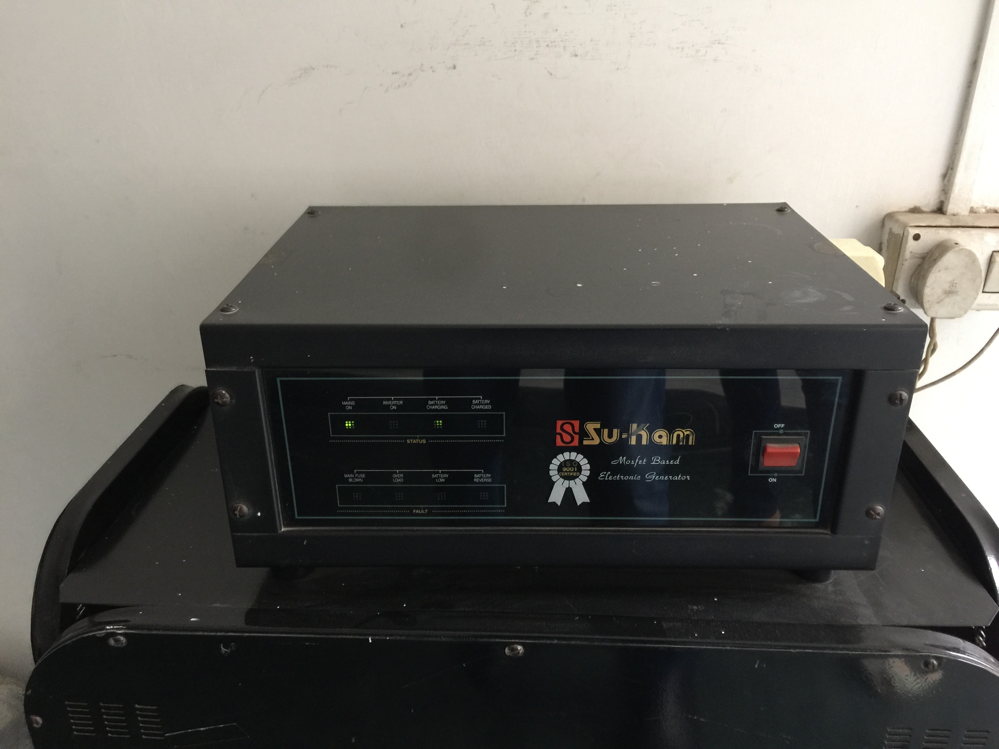 Su-Kam's first MOSFET-based inverter — India's first. Design began in 1998, first commercial units shipped in 1999, fully workable production-scale version by 2000.
This is Part 01 of Source Code of an Industry — a series written from real production-era inverter control technology, so the engineering story of how India's inverter industry actually began is not lost.
Between 26 May 2003 and 31 October 2017, I filed seventy-seven patent applications at the Indian Patent Office as founder of Su-Kam Power Systems. That portfolio is a matter of public record and is covered in a separate post in this series.
But the two inventions that actually created India's inverter industry — India's first MOSFET-based inverter (design started 1998, commercial 1999, fully workable and scaled by 2000) and India's first microcontroller-based inverter (2001) — are not in the 77-patent list. They predate it. They were built before Su-Kam had a patent programme. If we had known then what we knew by 2003, they would have been the first two entries.
This is the story of what came before the patents.
From Cable TV to inverters — 1998 to 2000
I did not start Su-Kam as an inverter company. Su-Kam was founded in 1988 as a Cable TV / MATV / CATV projects business — installing common antennas, VCRs, and cable distribution systems for hotels, multi-storey buildings, and later Air Force and Army stations. Through the early 1990s Su-Kam manufactured CATV amplifiers, modulators, directional couplers, and held the India distributorship of Echostar satellite receivers for Doordarshan.
The inverter work began in 1998 as a side experiment, while I was still running the Cable TV business. It started from a personal power-cut problem — Indian homes needed a proper backup solution and the existing market was not offering one.
From day one, I made a fundamental technical choice: the inverter would be built on MOSFET topology, not on the bipolar transistors that every other Indian inverter workshop was using. This decision alone set us apart. But it also meant the R&D took time. It took us roughly two years to build the first truly workable MOSFET inverter. There were no reference designs to copy, no local component supply chain for MOSFETs, no engineers with experience of MOSFET power electronics at Indian voltages. Everything had to be figured out from first principles.
In 1999, we launched our first commercial inverter — still refining the design in the field, but out in the market.
By 2000, the design was fully workable and manufacturable at scale. That year we scaled up in a big way — and I closed the entire Cable TV business to focus Su-Kam 100% on inverters and power backup. This is the pivot moment. Everything after 2000 in the Indian inverter industry was written on the MOSFET platform we had spent two years building.
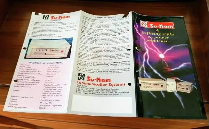 The first Su-Kam MOSFET inverter — industrial design and physical form. Designed personally by me at Su-Kam.
India's inverter market in 2000
The Indian inverter market in 2000 was not really an industry. It was a scatter of small workshops, mostly in Kolkata, building bulky transistor-based inverters. The products were heavy, hot, unreliable, and short-lived. There was no branded national manufacturer. There was no service network. There was no R&D. The concept of a "Home UPS" — combining inverter and UPS in one box for domestic use — did not exist.
And crucially, there was nothing to copy.
Inverters were not a European product because Europe had a stable grid. China was not yet an electronics manufacturing power. The only reference designs in circulation globally were RV (recreational vehicle) inverters and marine inverters — deliberately simple products with no battery charger, no grid-interaction logic, no protection intelligence. Useful as a starting point, but nowhere close to a Home UPS for the Indian market with its unstable grid, wide voltage swings, and long power cuts.
We had to design everything from first principles.
Invention 1 · 1998–2000 — India's first MOSFET inverter
Design began in 1998. First commercial units shipped in 1999. Fully workable, production-scale version by 2000. Under my leadership at Su-Kam, we built India's first MOSFET-based inverter — and that first generation was fully analogue. There was no microcontroller. All timing, regulation, changeover, and protection was done with discrete analogue control circuitry.
The single biggest technical decision, made in 1998, was to move away from bipolar transistors — which every other Indian inverter of that era used in a push-pull output stage — and build the whole product on MOSFETs. MOSFETs were considered exotic and expensive in India at the time. But they offered three properties the Indian market urgently needed: dramatically higher switching efficiency, far lower heat dissipation, and much smaller physical footprint.
Replacing transistors with MOSFETs was not a component swap. It required a full topology redesign, a new gate-drive circuit, new thermal management, and new protection logic. That is why it took us two years of R&D from 1998 to 2000 to get to a truly workable design. There were no reference schematics for Indian conditions, no local supply of the right MOSFETs, and no engineers with prior experience of MOSFET-based mains-frequency inverters at Indian voltage and load profiles.
The result was the first Indian inverter built on MOSFET topology — smaller, cooler, more efficient, and more reliable than anything else in the Indian market.
Independent media has documented this. As APN News summarised in its Su-Kam retrospective: "Su-Kam manufactured India's first MOSFET-based inverter." The Suvastika digital archive records that Su-Kam "brought MOSFET, microcontroller and DSP sine-wave technology into everyday inverters before anyone else in India." Deccan Herald, India Today, Silicon India, Economic Times, YourStory and Zee News have all reported the same founding story over two decades.
Within eighteen months of our launch, every serious Indian inverter maker was migrating to MOSFETs. The Kolkata transistor era ended. The industry followed us.
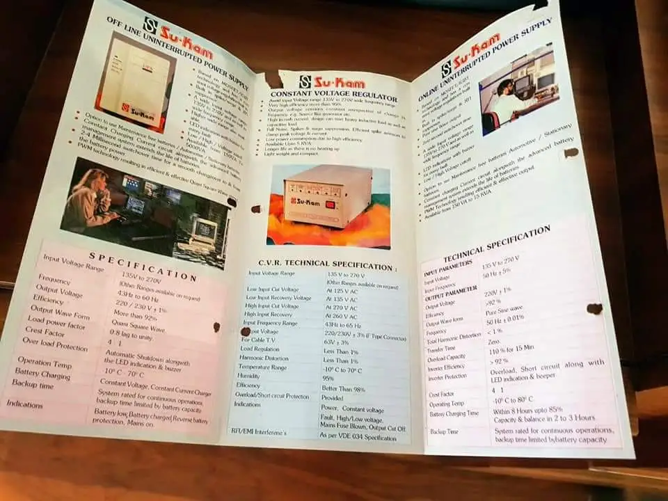 Su-Kam's first inverter product catalogue — the first for a MOSFET-based Indian inverter.
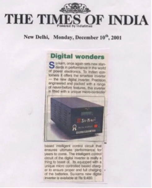 The first newspaper coverage of the Su-Kam inverter — the beginning of a national conversation about power backup that had not existed before.
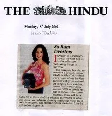 A second newspaper cutting from the same era — the Indian press recognising, in real time, that a new industry was being built.
Invention 2 · 2001 — India's first microcontroller-based inverter
Once the MOSFET topology was stable, the next question was: can an inverter think?
The same year, we committed to microcontroller control. I was actively involved in selecting the chip. We evaluated several 8-bit families and chose the Microchip PIC16F72. In 2001 we launched India's first microcontroller-based inverter.
This was a fundamental architectural change. Every function that had previously been implemented in discrete analogue circuitry — output regulation, mains sensing, changeover timing, low-battery cutoff, overload detection, short-circuit protection, charging control — was now written as firmware running on an 8-bit microcontroller.
The advantages were immediate and permanent:
- Precise, repeatable timing that did not drift with temperature or component tolerance
- Programmable protection thresholds — the same PCB could serve multiple product variants by loading different firmware
- Self-diagnostics — the microcontroller could report its own state via LED codes and, later, via LCD/LED displays
- Field-upgradable behaviour without hardware rework
- Dramatically simplified PCB with far fewer components — lower cost, higher reliability
- A software platform — from now on, product differentiation could be done in firmware, not just hardware
The PIC16F72 architecture we introduced in 2001 became the backbone of Su-Kam's product line for the next fifteen years. The lineage is directly verifiable in our internal records: the Digital UPS 1000 series firmware files still in production as recently as September 2023 carry the identifier M72 in their filenames — a direct reference to the PIC16F72 family that started with the 2001 design. That is architectural continuity across two and a half decades.
And once again, the industry followed. Within a few years, microcontroller-based inverters were the default across every serious Indian brand.
2002 — Government recognition of the R&D unit
In 2002, the Department of Scientific and Industrial Research (DSIR), Government of India, formally recognised Su-Kam's in-house R&D unit. This was the first government-recognised in-house R&D unit in India's power backup sector. No competitor had one.
The recognition was not a marketing certificate. It was a formal statement from the Government of India that Su-Kam was doing systematic industrial research and development in a category where systematic R&D had not previously existed.
This is what made the patent programme possible. You cannot file patents without disciplined R&D, laboratory infrastructure, documented invention disclosures, and prior-art searches. The 2002 DSIR recognition was the institutional foundation on which everything that came after was built.
2003 — The patent programme begins
The first patent I filed was on 26 May 2003 — application 722/del/2003, titled Digital Signal Processing Sine Wave Inverters, later granted as Patent No. 241612.
A detail worth noting: this first patent was filed under the applicant name SU-KAM COMMUNICATION SYSTEM LTD — the original corporate identity from the company's cable TV era. The first three patents (2003–2004) all carry this name. From 2006 onward the applicant name changes to SU-KAM POWER SYSTEMS LTD. The patent record itself documents the company's transition from communications to power electronics.
Over the next fourteen years, from May 2003 to October 2017, we filed 77 patent applications — the subject of Part 02 of this series.
Why the two most important inventions are not in the patent list
Because in 2000 and 2001, patents were not on my mind. Building a working product that solved a real Indian problem was on my mind. The patent discipline came later — after 2002, after the R&D unit was recognised, after we had built enough to know that what we were building was original.
The 77 patents are what came after the two inventions. The two inventions are what started the industry.
The proof stack
This is not a memoir claim. Each element of this history is externally verifiable:
- MOSFET inverter — external media proof: APN News Su-Kam retrospective; Deccan Herald; Suvastika digital archive; Silicon India; YourStory; Wikipedia
- Microcontroller architecture continuity: Su-Kam Digital UPS 1000-12V LED firmware, filename convention
M72-0x000d, dated 18 September 2023 — architectural lineage directly traceable to the 2001 PIC16F72 design - DSIR recognition (2002): Government of India public record
- 77 patents: Indian Patent Office public search at iprsearch.ipindia.gov.in
- India Today "Innovation of the Decade": plastic-body Chic inverter (covered in a further post in this series)
- 100 KVA inverter (2005) and Power on Wheels demo truck: internal photo archive and dealer network records
- Verified digital archive: solarmanofindia.com and invertermanofindia.com
Every claim in this post is either backed by an independent media report, a government document, a patent office filing, or an internal engineering file that is still on our servers. Nothing depends on memory alone.
What Source Code of an Industry covers next
This anchor post sets the historical spine. The rest of the series takes the reader through the technical, product, and industry-shaping decisions that followed — each with its own patents, products, and proofs:
- Part 02 — Seventy-seven patents: the R&D legacy of Su-Kam Power Systems, 2003 to 2017
- Part 03 — The plastic-body inverter: how Chic became India Today's "Innovation of the Decade"
- Part 04 — From modified sine wave to pure sine wave: DSP inverters and the second architectural shift
- Part 05 — Home UPS: creating a product category that did not exist
- Part 06 — High-frequency lead-acid battery charging (Patent 286639) and the battery management story
- Part 07 — The MPPT solar charge controller (Patent 292773) and India's first hybrid solar PCU
- Part 08 — The 100 KVA inverter (2005) and Power on Wheels: proving Indian technology to the Indian market
- Part 09 — Brainy Touch: India's first touchscreen, Wi-Fi-enabled solar PCU
- Part 10 — Application-specific power backup: fuel dispensers, lifts, ATMs, treadmills, telecom towers
- Part 11 — Manufacturing IP: the machines we invented to make our own products
- Part 12 — Exports to 90+ countries: the first Indian power electronics company to go global
- Part 13 — The five 2017 forward-looking provisional filings and what they were meant to build
- Part 14 — Su-vastika: 25 further patents (2019–2024) continuing the lineage, taking the total to 102
- Part 15 — What the industry got right, what it got wrong, and where Indian power backup goes from here
Disclaimer: This post documents work executed by Su-Kam Power Systems Limited between 1988 and 2018. Su-Kam was placed in liquidation by NCLT order dated 3 April 2019. Kunwer Sachdev has had no role in Su-Kam management since then. This blog is not published on behalf of, nor is it an endorsement of, any person or entity currently carrying on business under the Su-Kam name.
More from the Knowledge Base
When the Ah Rating Disappears: How Local Battery Brands Hide the Number That Matters Most
7 Jun 2026
The Charging Current Nobody Prints on Your Inverter Battery — And Why People Are Dying
7 Jun 2026
6 Questions You Must Ask Before Buying an Inverter Battery in India
7 Jun 2026
How Much Backup Do 150Ah and 200Ah Batteries Really Give? My Lab Tests, in Plain Words
7 Jun 2026